Description
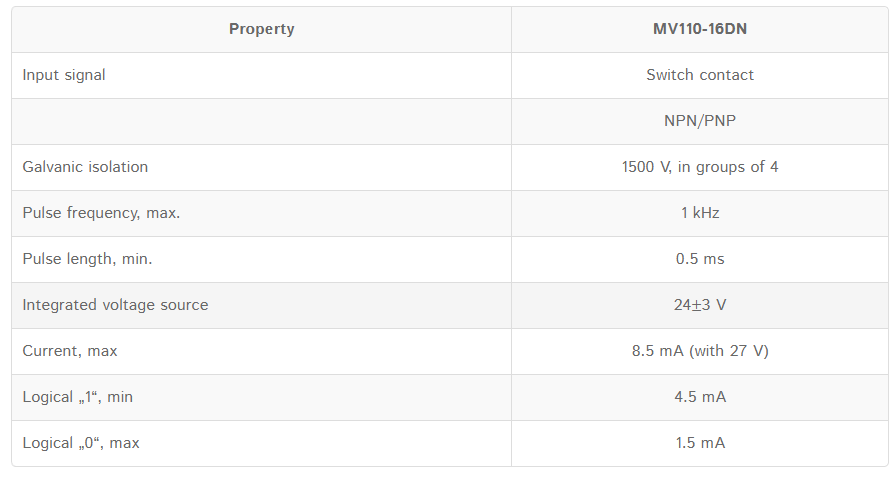
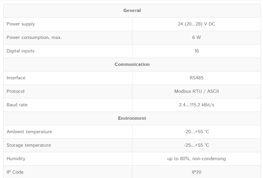
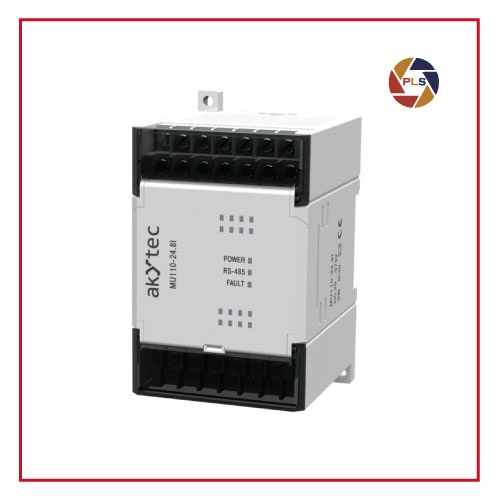
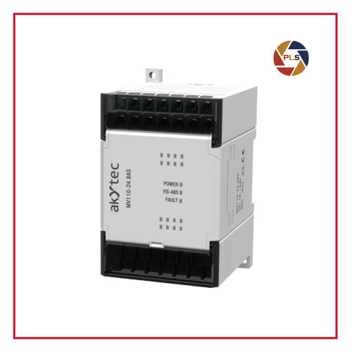
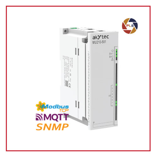
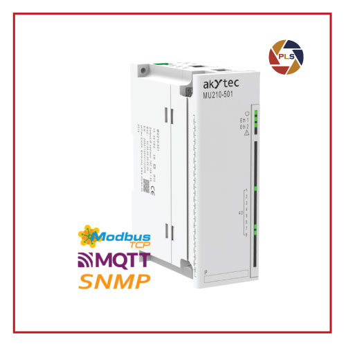
MV110-24 16DN Digital Input Module
The digital input module MV110-24.16DN has 16 digital inputs able to connect switch contacts as well as NPN or PNP transistors. All the inputs are galvanically isolated in groups of 4. To communicate the input data to a controller, a serial RS485 port and Modbus RTU/ACSII are at your disposal. The module requires 24V DC input power and can operate in the temperature range between -20 and +55 °C.
Contact Us for more Information.